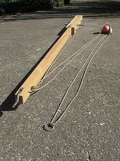
Trigger Assembly
After the trebuchet throwing arm is pulled down as far is it can go in
preparation for a launch, the
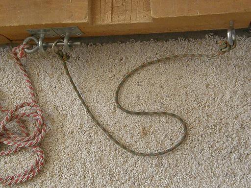
cord in the picture with the ring on the end of it is passed over the top
of the arm, then down between the two eye-bolts; a pin attached to the red
and white trigger rope is passed though one eye-bolt, the ring, and then the
other eye-bolt. The throwing arm is slowly allowed to rise until the cord
has tension on it; after that all that needs to be done is pull the red/white
trigger rope to pull the pin and the launch is under way.
The launch trough is directly under the throwing arm; without a design like
this, which has anchor points on either side of the launch trough, you would
be forced to have the trigger mechanism to one side. That would pull
the throwing arm to one side (not much, but enough) and adversely affect
the smoothness of the throw; the arm would actually be vibrating sideways
slightly during the launch.
Throwing Arm Assembly
 The throwing arm has a prong on the end to hook the sling ring. It is from
a back yard gate locking hardware set - the bar that slips into the latch.
The original prong had a small ball welded to the end of it, I sawed it off
and filed down the end of the prong.
The throwing arm has a prong on the end to hook the sling ring. It is from
a back yard gate locking hardware set - the bar that slips into the latch.
The original prong had a small ball welded to the end of it, I sawed it off
and filed down the end of the prong.
The sling is made from a sliding pouch and one long, continuous piece of
cord. The reason for this is that any time any parameter is changed (weight
of object thrown, the weight of the counterweight, relocating the pivot point
in the throwing arm) the length of the sling must be adjusted to ensure an
optimal launch angle. Without an adjustable system, you'd need to have a lot
of pieces of rope of different lengths to change the sling length.
With the system shown here, a combination of a double-overhand slip knot
(which is at one end of the rope) and an overhand loop that can be tied
at any point, provides the ability to lengthen or shorten the total sling
length as needed. The excess cord is run through a hole near the end of the
throwing arm, then down to a boat cleat screwed
into the throwing arm and wrapped between the cleat and the axle.
Sliding Sling Pouch
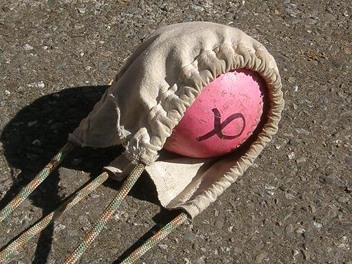 The sling pouch can slide along the sling; there are two channels of cloth
that are folded over the cord and sewn. When the sling length is changed,
the pouch can be moved along the cord until all four sections of cord supporting
the pouch are the same length.
The sling pouch can slide along the sling; there are two channels of cloth
that are folded over the cord and sewn. When the sling length is changed,
the pouch can be moved along the cord until all four sections of cord supporting
the pouch are the same length.
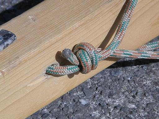
Double Overhand Overhand Loop Detail
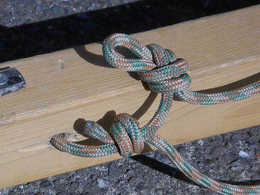 The overhand loop acts as a brake on the cord running through the double overhand
knot; the loop determines how much cord is in the sling.
The overhand loop acts as a brake on the cord running through the double overhand
knot; the loop determines how much cord is in the sling.
Storing Excess Cord
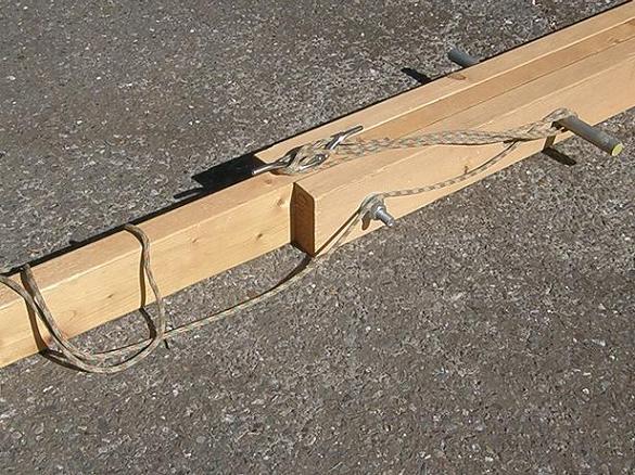 As cord is taken out of the system, depending how much is needed to get
the optimal sling lenght, it can be taken up here by wrapping it between
the axle and the cleat.
As cord is taken out of the system, depending how much is needed to get
the optimal sling lenght, it can be taken up here by wrapping it between
the axle and the cleat.
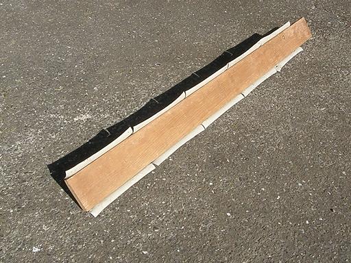
Launch Trough
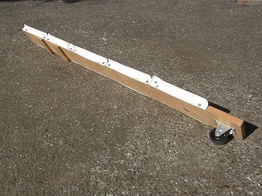 The launch trough is a surprisingly important part of the system. It
ensures that the thrown object a) is kept on a straight path in the early
stage of the launch and b) accelerates
up until lift-off from a smooth surface. If this piece is neglected the thrown
object will bump along (probably hitting the carriage frame) and will not
make much of a flight.
The launch trough is a surprisingly important part of the system. It
ensures that the thrown object a) is kept on a straight path in the early
stage of the launch and b) accelerates
up until lift-off from a smooth surface. If this piece is neglected the thrown
object will bump along (probably hitting the carriage frame) and will not
make much of a flight.
The sides are made of linoleum scrap and held in place with tacks.
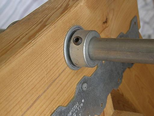
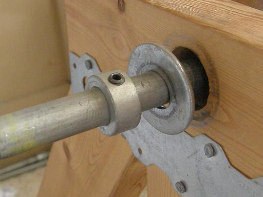
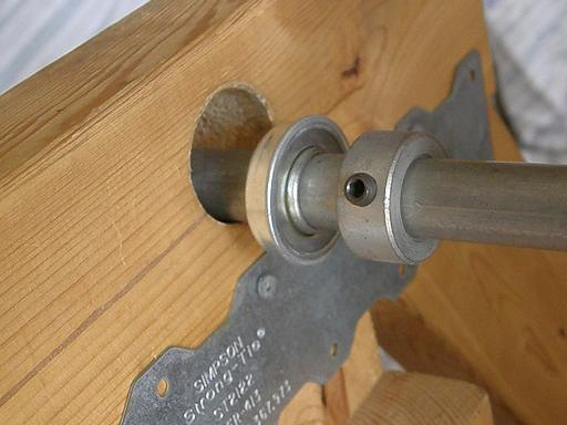 The axle rotates on bearings inserted into the carriage, on both sides.
The bearings are inset into the carriage, and are held in place by collars
mounted on the axle.
The axle rotates on bearings inserted into the carriage, on both sides.
The bearings are inset into the carriage, and are held in place by collars
mounted on the axle.